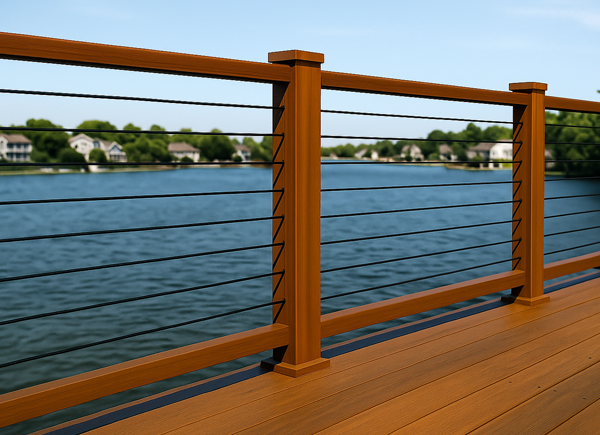
DeckWise® WiseRail® Cable Railing for Wood Posts introduces a new and improved premium railing option for builders and homeowners seeking refined quality without bulky hardware. The redesigned WiseRail® Legacy and WiseRail® Estate systems remove the oversized nuts, bolts, and turnbuckles found in traditional cable rail setups. What remains is a minimalist, modern, high-strength system with crisp lines and a clean, contemporary profile.
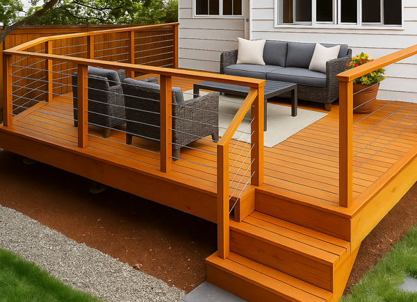
WiseRail® WiseCable® systems are designed to bring open, unobstructed views to any space, outdoors or in. Whether framing the edge of a backyard deck or adding a modern touch to an interior staircase or loft, these sleek cable rail systems offer a clean, modern aesthetic without sacrificing safety. Their low-profile design keeps sightlines wide open, making any space feel larger, brighter, and more connected to its surroundings.
Each rail fitting is proudly “Made in the USA” from 316L marine-grade stainless steel and precision-machined in our Florida DeckWise® manufacturing facility. WiseRail® Cable Railing systems are crafted from solid stainless-steel rod stock, expertly turned on advanced CNC Swiss lathes for unmatched accuracy. Every hardware component is engineered for long-term corrosion resistance, smooth assembly, and reliable cable tension. The result: clean lines, durable finishes, and cable runs that lock in place, and stay that way.
Whether you're a builder demanding excellence or a homeowner with a taste for the refined, DeckWise ® cable railing kits are the finishing touch your project deserves.
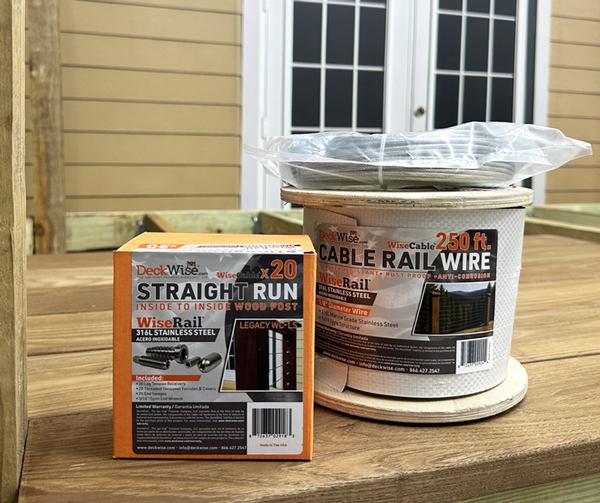
Accessories such as stainless steel cable wire spools (Stainless or Black), precision cable cutters, and pro-grade installation tools sold separately.
| Kit Series | Model # | Straight Run | Stairs |
|---|---|---|---|
| WiseCable ® Legacy | WR-LS | ||
| WiseCable ® Estate | WR-ESS |
NOTE: These two cable rail systems are not compatible with any DeckWise® CableRail® components or fittings manufactured prior to August 2025.
*All kits are sold for wood posts as straight runs or for stairs. Patent Pending.


Installing a wire cable railing system is best performed as a two-person project to ensure accuracy, safety, and ease of handling throughout the process.
WiseRail ® CableRail ® American Made cable rail hardware fittings are specifically designed for level-run installations using 4"x4" or 6"x6" wood posts (minimum actual dimension of 3½" square). Each hardware pack contains the necessary components for runs of 1/8" stainless-steel cable . To complete your project, be sure to purchase the appropriate number of infill pack for your desired railing height:
All hardware is manufactured in the USA at the DeckWise facility from 316L marine-grade stainless steel, providing exceptional resistance to rust, corrosion, and extreme weather, ideal for both interior and exterior applications, including coastal environments.
Before purchasing, take time to measure your layout, estimate materials, and plan for the number of runs, post placements, and cable lengths. It's always a good idea to order extra materials to account for cutting errors or on-site adjustments, especially wire cable rolls and swage terminals, which may be consumed during installation or due to mistakes.
If you need assistance with estimating materials or planning your layout, our support team is available to help at 941-896-9851 .
For most deck rail wood post systems, a minimum post size of 4x4 (3-½" actual) is required to withstand the tension applied by the wire cables. All terminating posts must be securely mounted to the structure to prevent loosening over time. A top rail is required, and we strongly recommend reinforcing it vertically beneath the top rail for additional support. A bottom rail is optional but may help distribute tension and reduce stress on the lower portion of the wood post assembly.
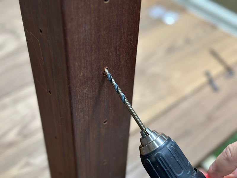
Measure 3-1/8" down from the bottom of the top handrail to mark the top-hole location. This location will be used as a reference point for the next hole - and that hole, will be a reference for the following one, and so forth. Each hole center mark must be 3-1/8" below the last.
To define the center of the post, use the supplied hole template. Or measure the width and divide by 1/2. Example: Wood post actual width is 3-1/2” wide, divided by 1/2, equals 1-3/4” inward marks the center of the post. Mark the center of the post. Do this on opposing sides of the post to accurately align holes for tensioner installation.
Optionally apply a strip of painter’s tape vertically down the center of the wood post for marking. It will also protect the wood post finish and avoid wood blowout when drilling.
For wood intermediate posts, you must install a Post Protector Insert Sleeve (sold separately) on each side where the cable passes through.
For intermediate metal posts (square tube or flat bar), predrilled holes will typically be provided to allow cable pass-through, eliminating the need for sleeves.
Metal intermediate cable braces are inserted between posts and feature pre-drilled holes for cable pass-through. Typical options include:
To maintain both structural integrity and code compliance, it is recommended that cables are spaced with no more than a 3-inch clear span between each row. For instance, when using 1/8-inch diameter cable, drill the holes at 3-1/8 inches on center to ensure consistent spacing while accounting for the cable's thickness.
In order to prevent deflection that could violate building codes, particularly the 4-inch sphere rule, cables must be supported along their lateral run. Support spacing should not exceed 48 inches (4 feet) between supports. Intermediate posts serve this purpose, but when minimizing the number of full-size posts, supplemental cable braces may be used.
These cable braces are inserted between posts and feature pre-drilled holes for cable pass-through. Typical options include:
Cable braces are sold separately and offer an effective solution to maintain cable alignment and prevent sagging without adding unnecessary bulk to the railing structure.
Note: In accordance with standard building codes, the space between the handrail and the top cable, between each cable, and between the bottom cable and the floor must be less than 4 inches at all times.
Before beginning your installation, check all local building codes, including city, county, and state regulations. Railing height and cable spacing requirements vary by jurisdiction. While we design our products to meet the most common standards, we cannot guarantee compliance with every regional code, so it is important to confirm with your local building authority.
General guidelines for handrail height:
Additionally, most codes require that no space within the railing system allow the passage of a 4" sphere, which governs vertical cable spacing and top/bottom clearance.
Important Safety Notice:
This cable railing system is not designed or intended to act as a containment barrier for pets, children, or any individuals who may attempt to climb, pass through, or otherwise access unsafe areas. It is solely intended as a guardrail system for fall protection and general use in accordance with applicable building codes.
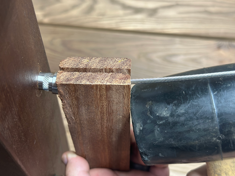
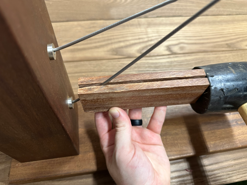
To avoid damaging the finish on Post Protector Sleeves during installation, a custom wood block should be used to help seat the sleeves securely into their holes. For best results, use a durable hardwood species when making the block.
Begin by cutting a thin wood block approximately 2 inches wide by 4 inches long and about 1 inch thick. On one of the 2-inch ends, cut a 3/16” groove to accommodate the cable wire. Then, on one of the 4-inch sides, cut another 3/16” groove. These grooves should intersect at the corner of the block to allow for both straight and angled cable insertion.
Legacy Straight/Level Runs: Insert the cable through the groove on the 4-inch side of the block. Align the end-grain of the block with the face of the Post Protector Sleeve, keeping them flush. Using a mallet, gently but firmly strike the block to seat the sleeve fully into the hole.
Estate Stair, Angle, & Pitch Runs: Use the corner where the 2-inch and 4-inch grooves intersect. Insert the angled cable into this corner groove, aligning the end-grain of the block with the sleeve face. Tap with a mallet to fully insert the Post Protector Sleeve without deforming or damaging the metal finish.
Optional Straight/Level Runs: Insert the cable through the groove on the 4-inch side of the block. Align the end-grain of the block with the face of the Post Protector Sleeve, again keeping them flush. Using a mallet, gently but firmly strike the block to seat the sleeve fully into the hole.
This custom block tool helps ensure a clean, damage-free installation and should be reused throughout the railing installation process.

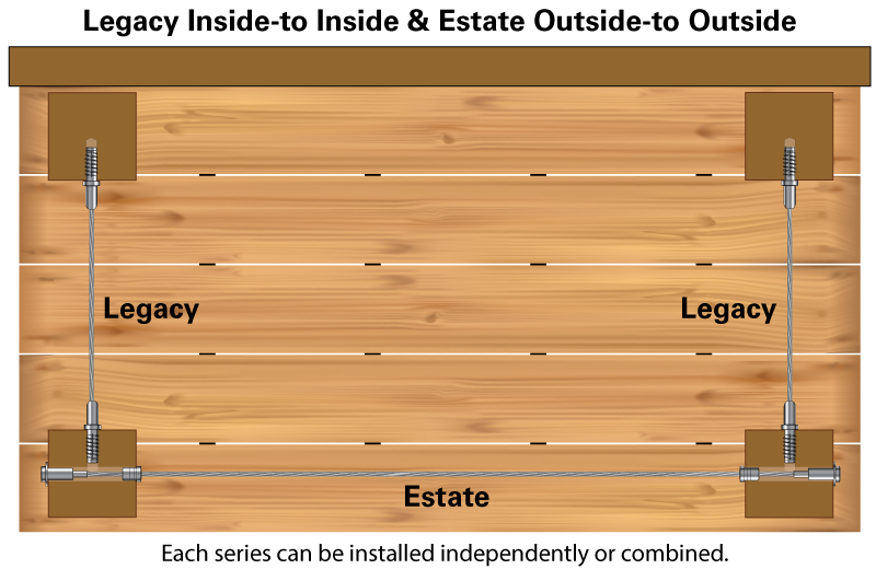
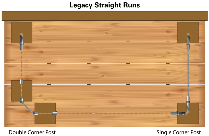
For those who value American craftsmanship and precision, the WiseCable® WiseRail® Legacy WR-LS Series is where strength meets sophistication. Designed exclusively for standard 4x4 and 6x6 wood posts, this inside-to-inside cable system offers a sleek, flush-mounted solution for straight cable runs where clean lines and unobstructed views are a must.
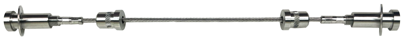
At its core is the concealed Lag Tension Receiver, paired with a precision-engineered Threaded Tensioner Ferrule, discreet Ferrule Cover, and field-swaged end cap. Every detail is intentionally subtle, crafted to minimalize itself into the post while delivering maximum tensioning power and a polished finish.
The result? A modern, streamlined, architectural aesthetic that elevates any space with refined simplicity and lasting performance.
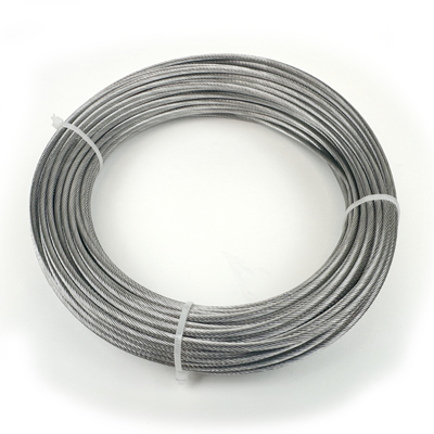
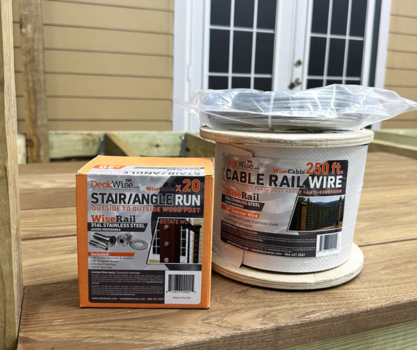
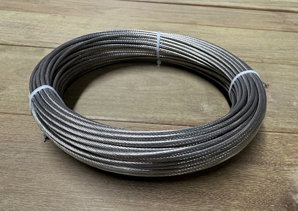
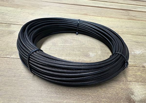
SOLD SERARATELY: Cable Rail Wire Spool – Available lengths: 100 ft., 250 ft., and 500 ft.
Patent Pending.
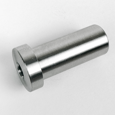
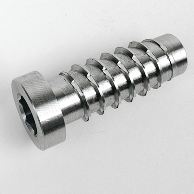
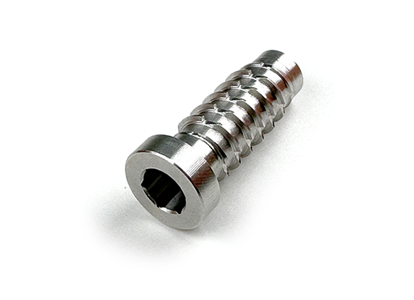
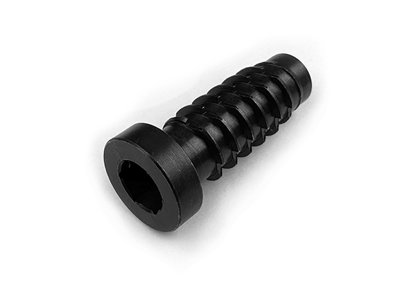
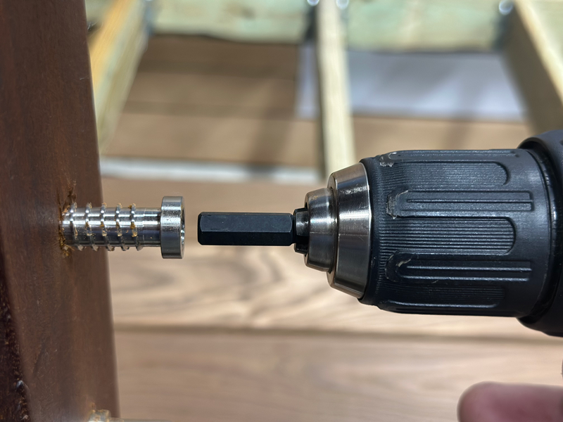
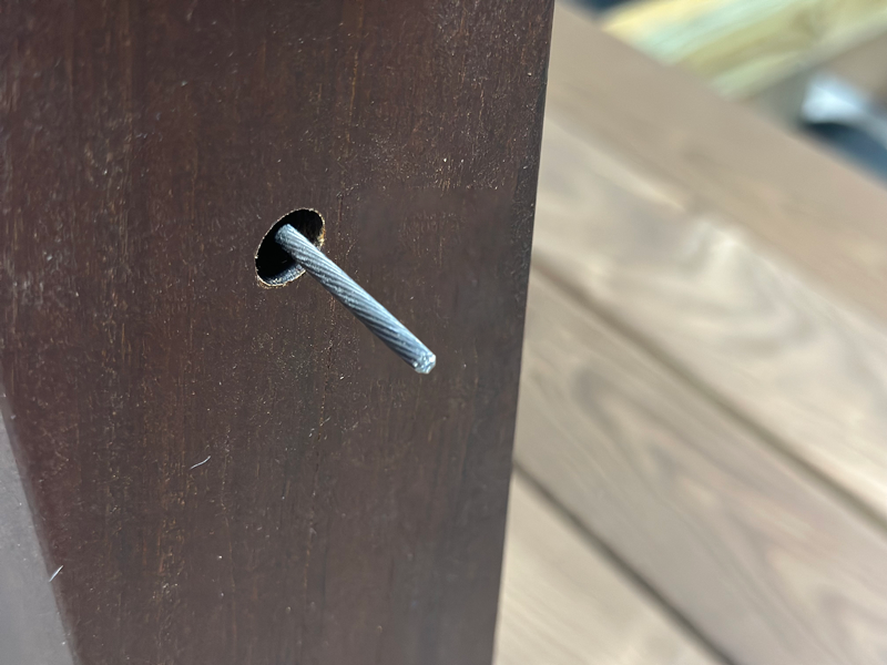
The Lag Tensioner Inside Receiver is a concealed tensioning anchor designed for wood post terminations in cable railing systems. It features an exterior auger thread that cuts directly into the post for a secure mechanical hold, and an internal threaded pocket that accepts the Threaded Tensioner Ferrule.
Installation is performed using a 5/16" hex key or a 5/16" hex driver, which will thread the receiver into a pre-drilled hole on the face of the wood post. Once installed, the Lag Tensioner allows the ferrule and Cable End Swage to be fully concealed inside the post, delivering a clean, modern, and professional appearance to the railing system.
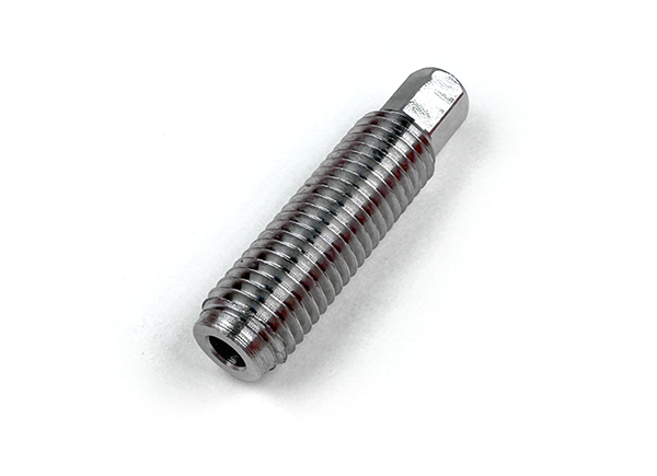
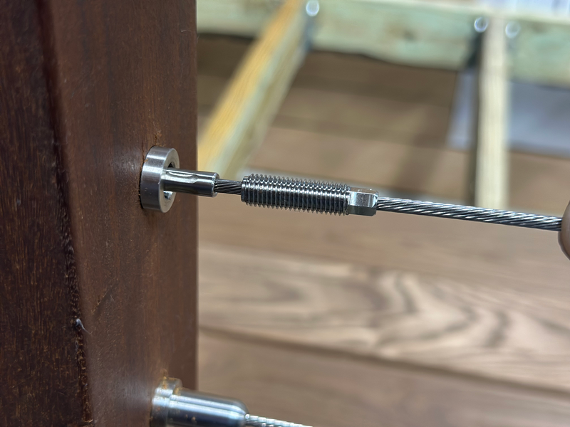
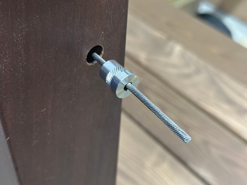
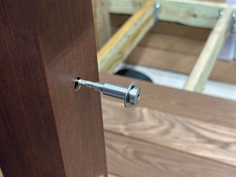
The Threaded Tensioner Ferrule is a precision-machined fitting designed to fit inside the Lag Tensioner Receiver and facilitate the tensioning of 1/8" cable wire. The cable passes directly through the ferrule, which does not require swaging or crimping, simplifying installation.
A 3/16" hex section is integrated into the ferrule body, allowing it to be rotated and tightened within the Lag Tensioner Receiver using the supplied 3/16” hex open end wrench. As the ferrule is turned, it presses against the Cable End Swage, drawing the cable tight and maintaining proper system tension.
To prevent thread galling and ensure smooth installation, it is recommended to apply anti-seize lubricant to the bottom 1/4 inch of threads on the ferrule before threading it into the receiver. This enhances performance and extends the life of the tensioning components.
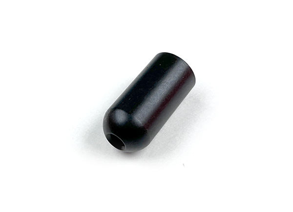
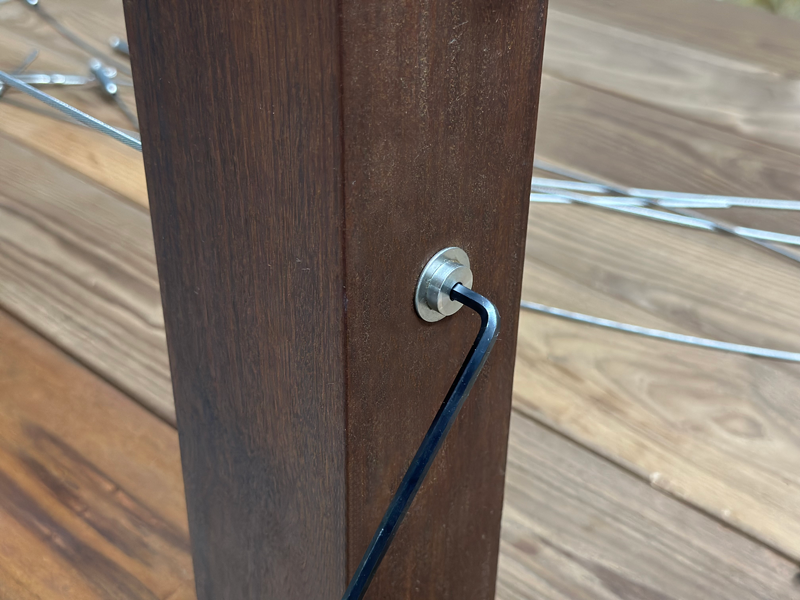
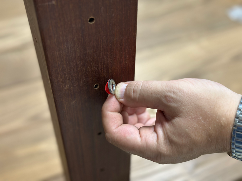
The Threaded Tensioner Ferrule Cover is a decorative component designed to conceal the exposed threads of the Threaded Tensioner Ferrule after installation. Once the cable has been fully tensioned, this cover is threaded into place over the ferrule, providing a clean, streamlined appearance.
Its sleek design adds a modern, finished look to the cable railing system, enhancing the overall visual appeal without interfering with the function of the tensioning mechanism.
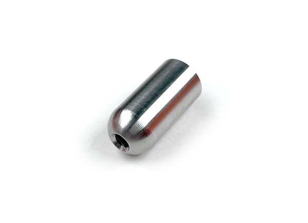
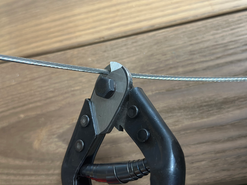
The Cable End Swage is a mechanical fitting used to secure the end of the 1/8-inch wire cable and serve as a physical stop for the Threaded Tensioner Ferrule during cable tensioning. It ensures a strong, reliable connection that holds the cable in place under load.
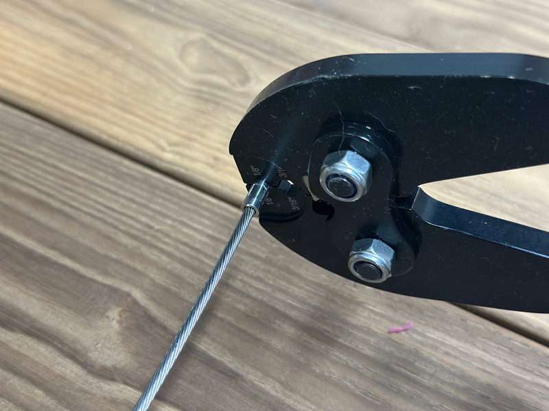
To properly install the swage, begin by positioning it onto the end of the cable. Crimp the fitting near the far end, approximately 1/8 inch from the bottom to begin the crimping. Then, rotate the swage 90 degrees and make a second crimp adjacent to the first. This dual-axis crimping method provides a secure, uniform hold and prevents the cable from slipping during installation or over time.
This fitting is critical for maintaining proper cable tension and is required for every terminated cable end using the WiseRail® tensioning system.
Installing Post Protector Sleeve (Sold Separately)
Level Intermediate/Pass-through Wood Posts
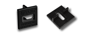
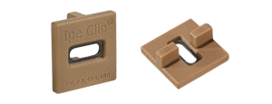
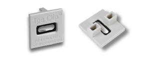
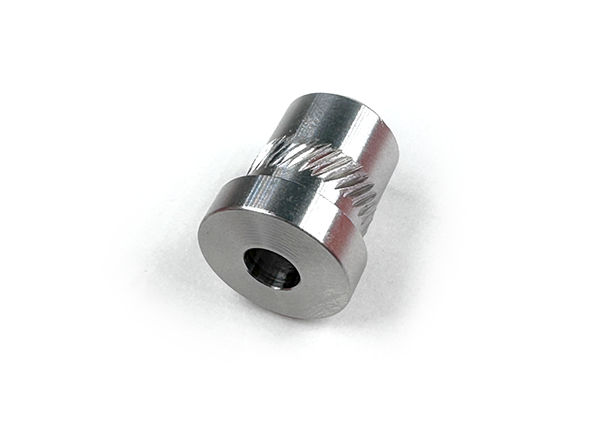
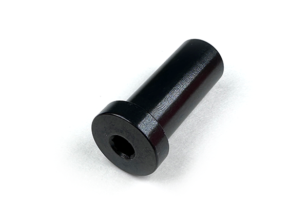
Post Protector Insert Sleeves are designed for use in pass-through wood posts to protect cable wire from friction-related wear. These sleeves create a smooth interior surface that allows the cable to glide easily through intermediate posts, reducing resistance and helping to maintain consistent cable tension throughout the run.
Each sleeve features an external grommet that covers the edge of the drilled hole, concealing any rough or uneven wood and providing a clean, finished appearance on the outer face of the post. These sleeves are essential for both function and aesthetics in a properly installed cable railing system.
Lag Tensioner Receiver – Terminating End Posts
Post Protector Insert Sleeve – Intermediate/Pass-Through Posts (Sold separately)
Note: Use the Drill Guide supplied with these instructions to accurately mark hole locations.
Using a 5/16" hex key or driver, thread the Lag Tensioner Receiver into the hole until the head sits flush with the wood surface. Its exterior auger thread cuts directly into the post, creating a strong mechanical hold. Once in place, the internal threads of the receiver accept the Threaded Tensioner Ferrule, which is swaged onto the end of the cable. This allows the cable to be tensioned securely from inside the post, delivering a clean, modern aesthetic with all hardware hidden from view. Ideal for straight cable runs, this setup provides both performance and refined style for any deck or railing project.
After all holes have been drilled in the terminating and intermediate/pass-through posts, measure the distance between the inside faces of the two terminating end posts. To this measurement, add 3-1/2 inches to account for the required hardware engagement on both ends. Cut the cable wire here. This total length will provide the correct cable length for each run, minimizing waste while ensuring proper fit during installation.
To begin, slide a Ferrule Cover onto the cut end of the cable, followed by a Threaded Tensioner Ferrule with the threaded end facing inward, toward the post. Next, place a Cable End Swage onto the cable wire and prepare to crimp it into place.
When crimping the Cable End Swage, begin by positioning the crimper approximately 1/8 inch from the bottom (farthest end) of the swage and make the first crimp. Then, rotate the swage 90 degrees and make a second crimp directly adjacent to the first. This two-position crimping method ensures a secure, properly formed hold on the cable wire.
This process should be repeated for every cable run, ensuring consistent and reliable termination before tensioning.
Before installation, it is recommended to apply anti-seize lubricant to the bottom 1/4 inch of threads on the Threaded Tensioner Ferrule to prevent galling and ensure smooth engagement.
Insert the ferrule into the first Lag Tensioner Receiver and finger-tighten it six full turns inward. Repeat this process on the opposite end of the cable by inserting the second Threaded Tensioner Ferrule into the corresponding Lag Tensioner Receiver on the opposing post, also finger-tightening it six full turns inward.
This initial positioning sets the cable in place and prepares it for final tensioning using the appropriate hex wrench.
Before threading the cable wire through the lateral holes of the intermediate (pass-through) posts, slide two Post Protector Insert Sleeves onto the cable for each intermediate post. The narrow ends of the sleeves should face the hole openings, ensuring proper orientation for installation. Repeat this process for every cable span between intermediate posts to ensure that all pass-through holes are properly protected with sleeves prior to seating and final cable installation.
Once the sleeves are positioned on the cable and aligned with their corresponding holes, press each Post Protector Sleeve into the drilled hole by hand. To seat the sleeve fully and flush, use a slotted wood block over the exposed portion of the sleeve and tap gently with a mallet until it is firmly in place.
Note: Post Protector Sleeves are sold separately. These components are essential for reducing cable wear, maintaining cable alignment, and creating a clean, professional finish.
To avoid damaging the finish on Post Protector Sleeves during installation, a custom wood block should be used to help seat the sleeves securely into their holes. For best results, use a durable hardwood species when making the block.
Begin by cutting a thin wood block approximately 2 inches wide by 4 inches long and about 1 inch thick. On one of the 2-inch ends, cut a 3/16” groove to accommodate the cable wire. Then, on one of the 4-inch sides, cut another 3/16” groove. These grooves should intersect at the corner of the block to allow for both straight and angled cable insertion.
Straight/Level Runs: Insert the cable through the groove on the 4-inch side of the block. Align the end-grain of the block with the face of the Post Protector Sleeve, keeping them flush. Using a mallet, gently but firmly strike the block to seat the sleeve fully into the hole.
This custom block tool helps ensure a clean, damage-free installation and should be reused throughout the railing installation process.
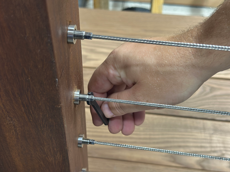
The proper sequence for tightening cable railings involves starting with the center cable and then outwards towards the top and bottom, alternating. This ensures even tension distribution and helps prevent damage or issues with the railing system.
There will typically be 11 fastener fittings on each post from top to bottom.
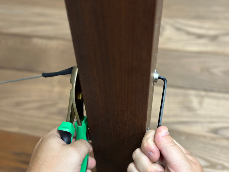
IMPORTANT: Use the neoprene sleeve with pliers or use cable wire grips to hold the cable while tightening.
NOTE: Be careful not to over-tighten your cables so that you can avoid experiencing deflection in your posts.
Installing a wire cable railing system is best performed as a two-person project to ensure accuracy, safety, and ease of handling throughout the process.
Installation Guide Corners Installation Installation Accessories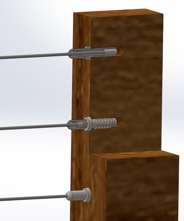
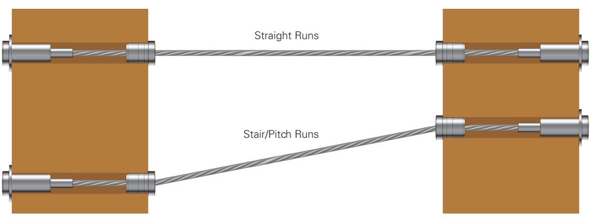
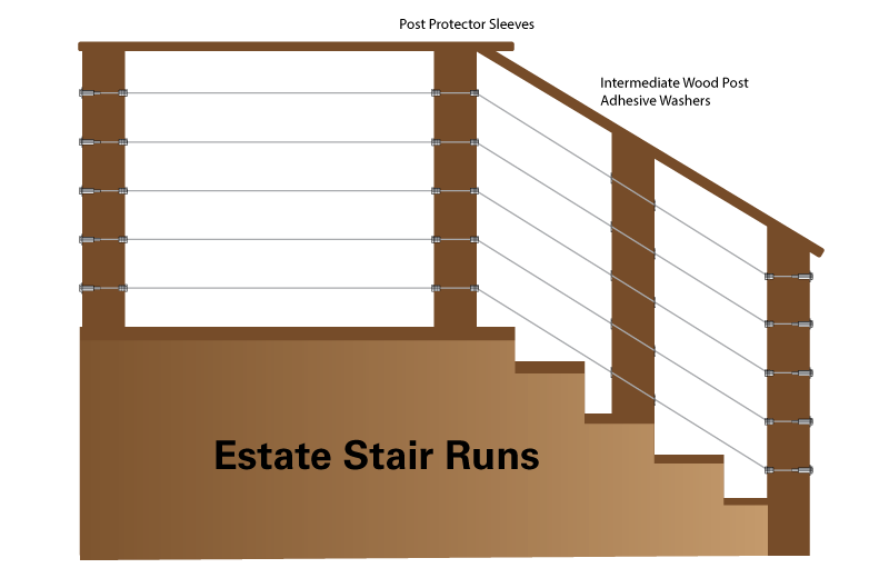
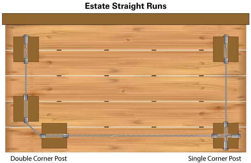
Crafted for those who demand American-made precision and enduring beauty, the WiseCable® WiseRail® Estate WR-ESS cable rail series transforms standard 4x4 and 6x6 wood posts into a striking architectural centerpiece. Designed for stairs, angles, and pitched applications, this outside-to-outside system also delivers clean, modern lines for straight cable runs.
Where other cable rail fittings display their nuts and bolts, Estate Series hardware proudly showcases its sleek minimalistic form and function. With rugged flush-mounted Tensioning Receivers, field-swaged Threaded Swages, every visible component is a testament to expert engineering and purposeful design. Crisp diagonal or horizontal cable lines define the space, framing the view without ever obstructing it.
When your design calls for strength, clarity, and unmatched craftsmanship, the WR-ESS Series answers the call with refined detail and a bold presence.
SOLD SERARATELY: Cable Rail Wire Spool – Available lengths: 100 ft., 250 ft., and 500 ft.
Patent Pending.
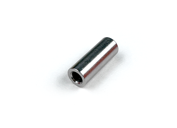
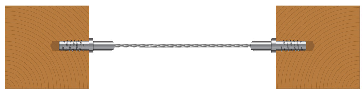
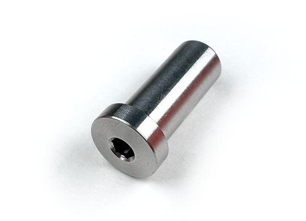
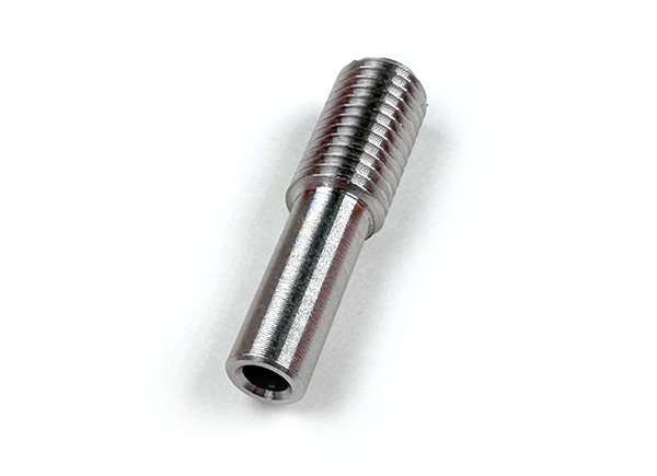
This cable railing system uses a through-post installation method, where the Tensioner Receiver is installed from the outside face of each terminating wood post. The receiver features a smooth shank for clean insertion and a threaded internal pocket designed to accept the Threaded Swage fitting.
This fitting is tightened from the outside of the post with the supplied 3/16” Hex Key. Once assembled, both the Tensioner Receiver and Threaded Swage are concealed inside the post, resulting in a sleek and modern finish.
Each Tensioner Receiver includes an external grommet designed to cover the edge of the drilled hole, effectively concealing any rough or uneven wood and providing a clean, finished appearance on the exterior face of the post.
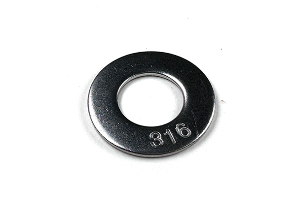
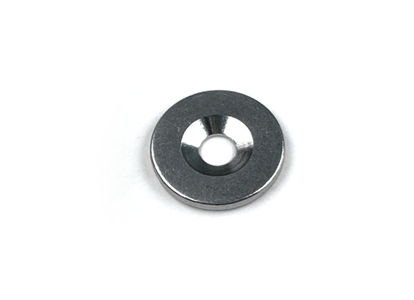
A Retaining Receiver Washer is included and must be installed over each Tension Receiver during assembly. This washer serves a critical function by distributing the tension load and preventing the receiver from embedding into the wood as the cable is tightened, thereby helping to preserve the post’s surface and maintain long-term structural integrity.
The Threaded Swage is a precision-machined, dual-purpose fitting designed to be crimped onto the end of 1/8" cable wire and installed inside the Tensioner Receiver. It provides both mechanical anchoring under load and enables internal tensioning by threading directly into the receiver.
As the Tensioner Receiver is rotated during final assembly, the Threaded Swage is drawn inward, effectively tightening the cable wire from within the post. This concealed tensioning method maintains a clean, sleek appearance on the exterior of the post.
To install, slide the Threaded Swage onto the cut end of the cable. Begin the crimping process approximately 1/8 inch from the upper threads on the swage. Make the first crimp, then rotate the swage 90 degrees and apply a second crimp adjacent to the first. This dual-axis crimping method ensures a secure, uniform grip on the cable and prevents slippage during installation and over time.
This fitting is critical for maintaining proper cable tension and is required for every terminated cable end using the WiseRail® tensioning system.
To prevent thread galling and ensure smooth installation, it is recommended to apply anti-seize lubricant to the bottom 1/4 inch of threads threading into the receiver. This enhances performance and extends the life of the tensioning components.
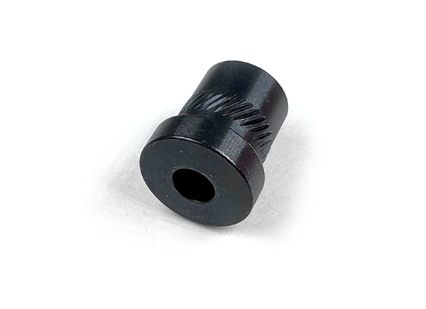
Post Protector Insert Sleeves are designed to be installed on the opposite side of the wood post from the Tensioner Receiver, where the cable wire exits or passes through the post. These sleeves serve a critical role in protecting the cable from friction-related wear by creating a smooth, low-resistance interior surface.
By minimizing contact abrasion, the sleeves help ensure consistent cable tension across the entire run and extend the life of the system. Each sleeve also features an external grommet that conceals the edge of the drilled hole, covering any rough or uneven wood for a clean, finished appearance on the post face.
Post Protector Insert Sleeves are essential not only for protecting the cable but also for enhancing the overall fit and finish of the railing system, making them a vital component in any well-executed cable rail installation.
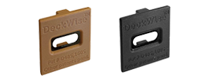
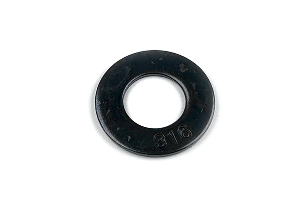
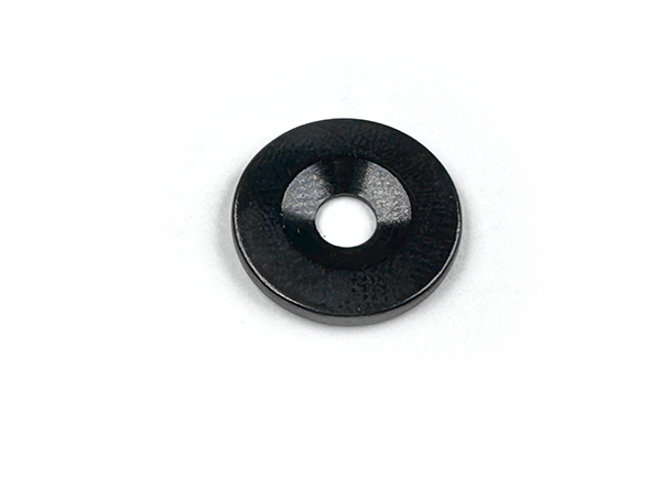
SOLD SEPERATELY: Adhesive Washers are non-structural, decorative components designed to enhance the visual finish of intermediate (pass-through) wood posts in stair and angled cable railing installations. These washers are applied to the outer face of the stair/angle post to conceal drilled cable exit holes, effectively covering rough edges and providing a clean, professional appearance.
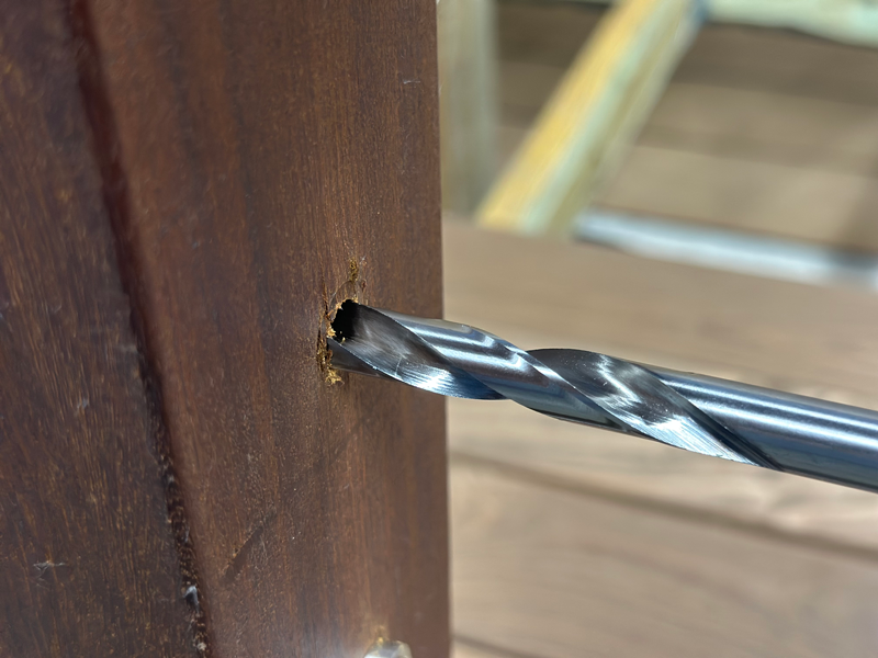
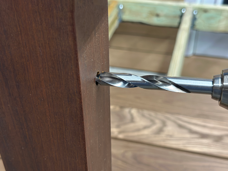
For proper application on stair/angle runs, intermediate wood post holes should be drilled at a 30- 37-degree angle through the entire post using a 3/16" or 5/32" drill bit. To minimize wood tear-out or chipping on the exit side, apply painter’s tape to the post face or place a scrap wood block behind the post during drilling.
Important: Adhesive Washers are for aesthetic purposes only. They do not provide structural support and must not be used in any load-bearing role. All mechanical strength and cable tension must be maintained using approved hardware and installation procedures.
Tensioner Receiver Side – Terminating End Posts
Post Protector Insert Sleeve – Opposing Side
Note: Use the Drill Guide supplied with these instructions to accurately mark hole locations.
Once all holes have been drilled in the terminating (and applicable intermediate pass-through) posts, begin by feeding the cable through the run. Starting from the bottom post and feeding upward typically provides the smoothest installation. As you thread the cable through applicable intermediate posts, install Adhesive Washers where needed.
Prior to feeding the cable through the top post, slide a Post Protector Sleeve on and feed approximately 12 inches of cable through the top terminating post. Crimp a Threaded Swage fitting onto this end of the cable using the recommended two-position crimping method. Then place a Retaining Receiver Washer onto a Tensioning Receiver, and thread the lubricated Threaded Swage into the receiver by four full turns.
Next, pull the cable back through the top post until the Tensioning Receiver is seated inside the post hole. Ensure the Retaining Receiver Washer sits flush against the outside face of the post.
At the bottom post, nearest the cable spool, pull the cable tight through the post to complete the full cable run. Once the cable is tensioned by hand, place a strip of painter’s tape or make a visible mark on the cable at the point where it exits the outside face of the post. Using cable cutters, trim the cable a few inches beyond this tape or mark.
Next, remove the cable from the post and make a final cut 1-inch inward from the original tape or mark. This trimmed length defines the proper position for attaching the Threaded Swage fitting. Before proceeding, double-check that all necessary Adhesive Washers are in place on the cable, this is your final opportunity to install these components before completing the assembly.
Crimp a second Threaded Swage onto the freshly cut end of the cable using the standard crimping method. Insert the second Tensioning Receiver, preassembled with its Retaining Washer, into the 1/2" hole on the outside face of the bottom post. Apply anti-seize lubricant to the threads of the swage, then insert it through the opposing 1/2" hole on the inside face of the post and begin threading it into the receiver to prepare for final tensioning.
Using the supplied 3/16" Allen key, rotate the Tensioning Receiver from the outside until the swage threads approximately four full turns, or just enough to hold it securely in place.
Remove the backing from any remaining Adhesive Washers and press them firmly against intermediate post holes to complete the visual finish.
To avoid damaging the finish on Post Protector Sleeves during installation, a custom wood block should be used to help seat the sleeves securely into their holes. For best results, use a durable hardwood species when making the block.
Begin by cutting a thin wood block approximately 2 inches wide by 4 inches long and about 1 inch thick. On one of the 2-inch ends, cut a 3/16” groove to accommodate the cable wire. Then, on one of the 4-inch sides, cut another 3/16” groove. These grooves should intersect at the corner of the block to allow for both straight and angled cable insertion.
Estate Stair, Angle, & Pitch Runs: Use the corner where the 2-inch and 4-inch grooves intersect. Insert the angled cable into this corner groove, aligning the end-grain of the block with the sleeve face. Tap with a mallet to fully insert the Post Protector Sleeve without deforming or damaging the metal finish.
Optional Straight/Level Runs: Insert the cable through the groove on the 4-inch side of the block. Align the end-grain of the block with the face of the Post Protector Sleeve, again keeping them flush. Using a mallet, gently but firmly strike the block to seat the sleeve fully into the hole.
This custom block tool helps ensure a clean, damage-free installation and should be reused throughout the railing installation process.
Note: These washers are decorative only and do not provide any structural or load-bearing function.
The proper sequence for tightening cable railings involves starting with the center cable and then outwards towards the top and bottom, alternating. This ensures even tension distribution and helps prevent damage or issues with the railing system.
There will typically be 11 fastener fittings on each post from top to bottom.
IMPORTANT: Use the neoprene sleeve with pliers or use cable wire grips to hold the cable while tightening.
NOTE: Be careful not to over-tighten your cables so that you can avoid experiencing deflection in your posts.
Installing a wire cable railing system is best performed as a two-person project to ensure accuracy, safety, and ease of handling throughout the process.
Installation Guide Corners Installation Installation Accessories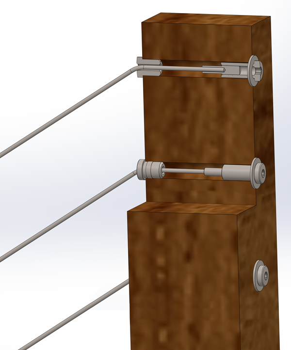
Use the guides below to view and download details, dimensions, and installation information regarding WiseCable ® WiseRail ® tensioners and fittings.
Before enjoying your new cable railing system, it's essential to ensure it meets all International Residential Code (IRC) standards as well as any local building codes. Safety and compliance should always come first.
In general, cable railing code requirements come from two different sources:

Once installation is complete, don’t just admire the look, inspect your system carefully to con-firm it’s safe and secure. Here’s what to review during your final walkthrough:

To keep your railing system looking and performing like new, follow these maintenance best practices:

When planning a cable railing system, it's essential to understand the building codes that apply based on the environment, residential or commercial. While many standards are shared across both types of projects, local building codes can introduce small but important variations. Always consult with your local code authority before finalizing your design or beginning installation.
Typically, horizontal cable railing systems must meet the following code criteria:

One of the most important and commonly referenced rules is the Sphere Rule, which governs the maximum allowable space between cables or other parts of the railing system.
What is the 4-Inch Sphere Rule?
This rule states that a 4-inch diameter sphere must not be able to pass through any opening in the railing. It’s designed to prevent small children from slipping through or getting stuck.
To meet this requirement, cable holes in wood posts are typically drilled 3-1/8” center-to-center. This spacing accounts for any deflection in the cables while still preventing gaps from exceeding the 4-inch maximum.
What is the 6-Inch Sphere Rule?
If your project includes stairs, the rule adjusts: a 6-inch sphere must not be able to pass through the open space between stair treads and the bottom edge of the railing system.
Ensuring your cable railing meets these guidelines isn’t just about compliance—it’s about creating a safe, durable, and professional-grade railing system.

When you need help, our knowledgeable U.S.-based sales reps are always ready to answer your questions and provide expert support. We're not just making cable railing, we’re backing it with real people, real service, and real American pride.