Order deck tiles and pedestals in accordance to the measurement of the total area to be tiled to determine the number of deck tiles and pedestals needed. Create a planning guide of the layout area with a grid pattern to scale for the size of the deck tiles.
Attention to, and inspection of hardwood deck tiles and pedestals must be completed prior to installation. Drawings of the deck tile pattern, layout grid, threshold starting point, and finished elevation should be shown on a architectural planning guide. Plans, CAD drawings and/or illustrations should be prepared and approved by an accredited architect or construction designer. Owner approval and sign-off of plans should be in writing and documented.
U.S. Patent Numbers D728,185, D738,589, 9,556,621, and 9,803,377. Other patents pending.

Verify all pedestals and tiles are in good condition, verify cavity elevations, desired top-of-pedestal heights and overall installation dimensions. Inspect the roof top substrate to confirm that it has been correctly prepared. If roof top preparation is the responsibility of others, notify the construction designer, contractor and architect in writing. Any deviations from the manufacturer's recommended installation guidelines will void warranty or create an unsafe surface.
Installation requirements for deck tiles and pedestals will vary per individual job site.
Any intended installation area of a hardwood deck tile pedestal system must fit tight inside the walls of the installation cavity and be restrained and contained. Deck tiles and pedestals will move if they are not tightly fit within containment walls. Any installation area must utilize – where applicable – parapet retaining walls, concrete dividers or other structural perimeter restraint capable of resisting lateral forces including seismic and wind. Blocking must be installed when elevations change height such as stepping up or down.
Perimeter "structural" framing and edging boards located at the outside of the perimeter must also be installed – where applicable – to provide restraint. No movement greater than 1/8th inch should be allowed at the perimeter of the deck pedestal system. Cumulative movement in excess of 3/16 of an inch will void the Altitudes Pedestal® System warranty.
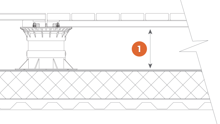
The cavity height is the space between the substrate and the bottom of the hardwood deck tiles. This area typically has drainage slope for water and can likewise be used to hide conduit running across the substrate surface. Services running inside the cavity can be easily accessed by pulling up a deck tile or two.
To determine the cavity height, first verify with the architect, general contractor or building owner what the finished height of the deck tile surface will be. Most often, this is determined by the height of threshold(s) located around the installation area.
Begin by taking the lowest threshold measurement from the actual construction area and compare to the architectural drawing for accuracy. Generally speaking, thresholds will have the shortest pedestals due to upward sloping from the center drainage areas. Drainage areas will have the tallest pedestals.
To determine the pedestal height at the threshold, mark the desired height of the finished deck tile height on the threshold wall. Measure the deck tile thickness (normally 1-11/16 inches thick), subtract the thickness of the deck tile from the finished deck tile height. This mark determines the minimum pedestal support height on the threshold wall. All remaining pedestal heights will be “level” with this mark. This is commonly referred to as the “Top of Pedestal Elevation.”
Once the minimum pedestal height is determined, set a laser level receiving unit (or transit water level) to read the pedestal height from the threshold. Moving along the containment wall perimeter, mark the threshold pedestal height approximately every 10-20 feet. Snap a chalk line on these marks as a reference line along the perimeter for pedestal installation.
When the finished elevation of the hardwood deck tile surface has been determined and the “Top of Pedestal Elevation” is established, the cavity will be recognized.
The number of pedestals required for your specific area will depend on the following:
The following formula can be used a guide. Always refer to your grid layout.
Deck Tiles on Length: 9 + 1 = 10
Deck Tiles on Width: 7 + 1 = 8
10 x 8 = 80 Pedestals Needed
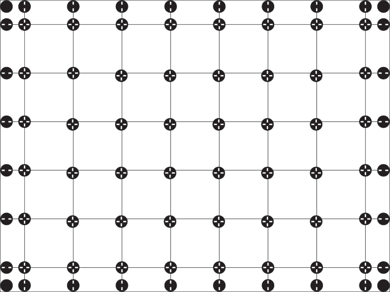
Order pedestals at a 3% overage to account for additional installation variances.
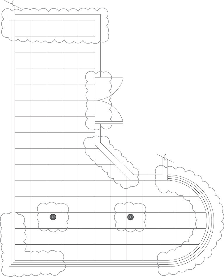
Create a Planning Guide. Transpose the construction site measurements onto a deck tile and pedestal Planning Guide. This will determine the number of deck tiles and pedestals needed for the installation area. Additional pedestals may be needed for radius placement, thresholds, corners, and diagonal wall placement including extra pedestals for around the installation perimeter.
To determine the number of deck tiles needed, take measurements of both the length and width of the deck installation area(s). Adding 3/16 of an inch for spacer tabs between deck tiles will give a more accurate estimation. This will also give the on-center dimension for the pedestals.
Installation of any anticipated heavy objects on top of the decking area such as planters, sculptures, hot tubs or industrial equipment must be supported directly by additional pedestals. These pedestals are in addition to the central deck tile pedestal system. Failure to adequately support any additional weight of any such structures or items may cause significant damage to the underlying structure, substrate insulation or waterproof membrane.
Additional pedestals may be needed for radius placement, thresholds, corners, and diagonal wall placement including extra pedestals for around the installation perimeter.
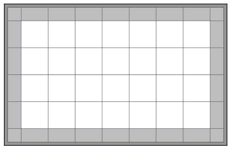
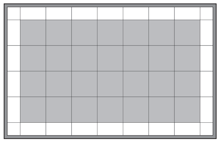
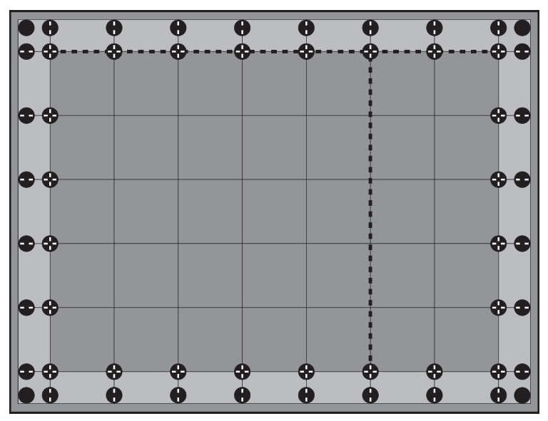
For proper installation, full deck tiles should be in the middle and cut deck tiles should be along the perimeter. All cut perimeter deck tiles should be of equal length and width.

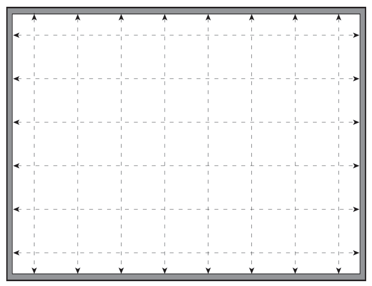
Begin by reviewing the Planning Guide to reference the cut deck tiles around the perimeter of the installation site. The length and width of the perimeter tiles will determine where the perimeter guideline goes. First, mark perimeter guidelines on the substrate of equal distance from the containment wall. These reference lines will represent the cut deck tiles around the perimeter.
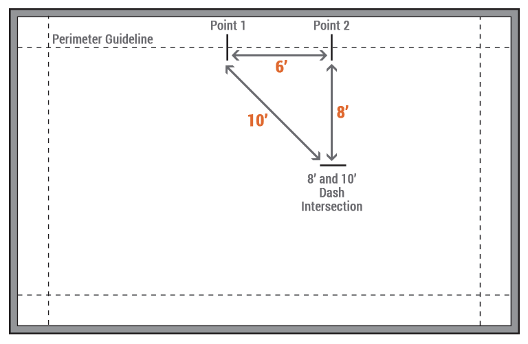
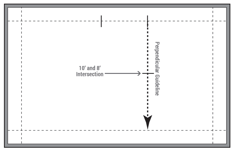
Using the 6-8-10 Rule, create a perpendicular guideline to the Perimeter Guideline. This will establish the starting point for full deck tiles. Reference the Planning Guide for the proper starting point of this guideline in accordance to deck tile layout.
With the 6-8-10 Rule, start by marking two points 6 feet apart on the perimeter guideline. From the first point, measure 8 feet out and make a dash; on the second point, measure 10 feet out diagonally towards the 8 foot mark and make an intersecting dash. The intersection of these two lines will create an exact perpendicular line to the perimeter guideline. To increase the accuracy of larger deck layouts, proportionally enlarge the triangle produced by the 6-8-10 Rule.
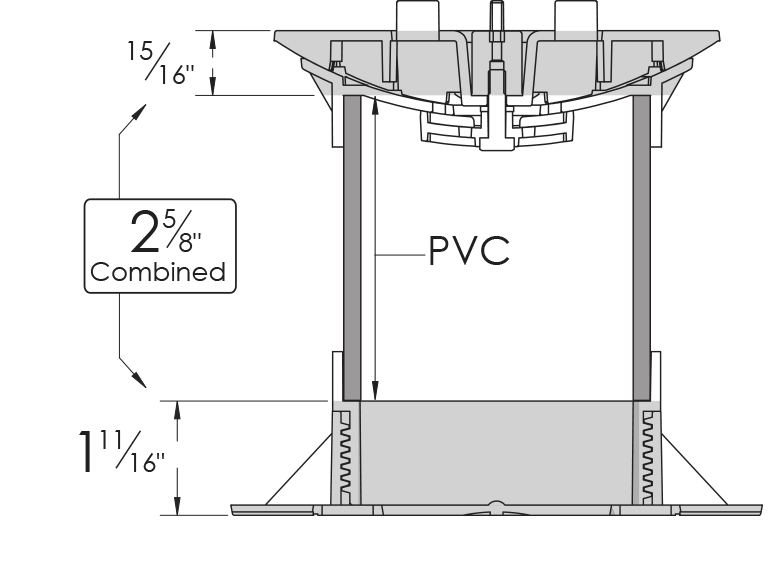
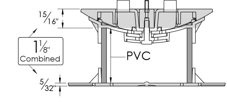
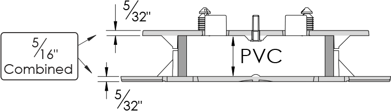
The Schedule 40 PVC pipe fits inside the cavity of the pedestal heads and the pedestal bases. To acquire the correct height of the PVC, subtract the head and base from the overall desired “top of pedestal” height/elevation for accuracy.
The screw-to-adjust base will provide final height adjustments or shims with the Stationary bases.
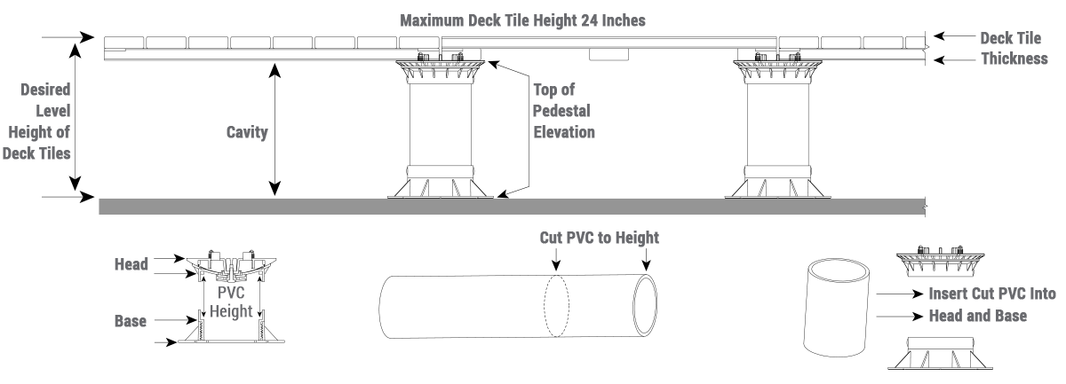
The PVC pipe fits inside the cavity of the pedestal head and the pedestal base. To acquire the correct height of PVC; the head base, and the nominal thickness of the deck tile must be subtracted from the finished elevation of the deck tile surface for accuracy. The screw-to-adjust base will provide final height adjustments.
The PVC “press fit” connection of the head and bottom screw-jack base requires no gluing.
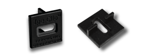
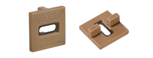
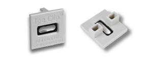
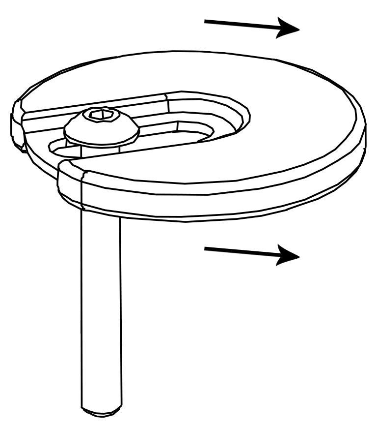
Deck tiles are secured to the pedestal with pine tree fasteners (rated up to 166 lbs. of wind hold-down strength) and our patented adjustable Lockit Down Washer™. The washer fits into the corner kerf cut slots of deck tiles which, in turn lock and hold down deck tiles to the pedestal head.
Insert the Lockit Down Washer™ into the corner kerf cut slot of all 4 hardwood deck tiles where they meet on a pedestal. First, slide a washer into 2 tile kerf corner slots and hand thread the 3/32" stainless steel screw into the stainless steel insert of the pedestal head. Install a 3rd deck tile by sliding the washer out of the way and place over the pine tree fastener. Next install the 4th deck tile onto the pedestal's 4th corner in the same manner. Once all 4 deck tiles are in place and levelness is checked, center the washer and securely tighten the screw for maximum hold-down.
To remove a deck tile: loosen the stainless steel screw and slide the washer to the side into adjoining deck tiles and out of the way. All 4 corners of the deck tile that is to be removed, will need to have the washer loosened and slid to the side for deck tile removal.

Pine tree fasteners additionally secure each deck tile to the pedestal head.
Pre-drilled holes under each deck tile precisly position each tile on the pedestal head.

Once the Perpendicular (Starting Point) Guideline and the finished elevation of the pedestal height have been determined, precisely measured grid lines must be laid out with chalk lines onto the substrate. Mark grid lines in both directions with chalk lines. Grid line intersections will spot the location of each deck tile pedestal. Use the Perimeter Guideline as a reference point to periodically check for square alignment.
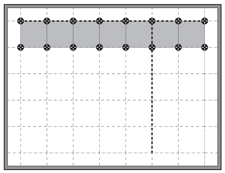
The Perimeter Guideline will be set with full deck tiles first. Start where the Perimeter Guideline and the Perpendicular (Starting Point) Guideline meet. The first 2 rows of pedestals will follow the Perimeter Guideline horizontally to the perimeter wall. (Later, pedestals will be placed along the Perpendicular (Starting Point) Guideline, creating a “T” shape.)
At the starting point, deck tile pedestals must be positioned where each measured grid line intersects the Perimeter Guideline. With a laser level receiving unit, measure each pedestal location for “Top of Pedestal Elevation” and cut the appropriate size of Schedule 40 PVC for each pedestal. Final level adjustments will be made with the screw-to-adjust base.
Continue installing pedestals down the Perimeter Guideline followed by deck tile placement onto the pedestals. Make finetune adjustments with the screw-to-adjust base as you go.
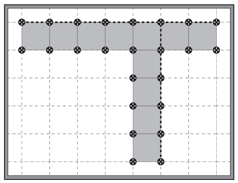
Once a row of full deck tiles has been placed on the Perimeter Guideline, pedestals and full deck tiles will be installed on the Perpendicular (Starting Point) Guideline. Continue installing 2 rows of pedestals down the Perpendicular (Starting Point) Guideline followed by full deck tiles as you go. This will form a “T” shaped pattern with the Perimeter Guideline.
With a laser level receiving unit, measure each pedestal location for “Top of Pedestal Elevation” and cut the appropriate size of Schedule 40 PVC for each pedestal. Adjust and level each consecutive pedestal marked around the perimeter wall. Fine-tune vertical height adjustments by twisting the adjust-to-level base.
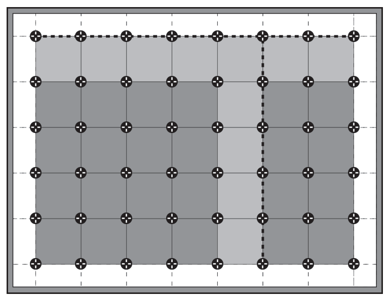
After all full deck tiles have been installed in the middle/center portion(s) around the “T” shape, the perimeter pedestals and cut deck tiles will be installed. Pedestals must be placed as close to the perimeter containment wall as possible. This means spacer tabs will need to be removed from the pedestal head. Use a hammer to punch the spacer tabs out.
Align the 2 remaining pedestal spacer tabs with the grid line; use the elevation marked on the perimeter wall to set the “Top of Pedestal Elevation” and check for level. A hand level or laser leveling unit may be used for this purpose. As the pedestals located along the grid lines are loaded with perimeter deck tiles, fine-tune vertical height adjustment can be made by twisting the adjust-to-level base.
Remove all 4 spacer tabs at corners when the incorporated pedestal tabs cannot be utilized.
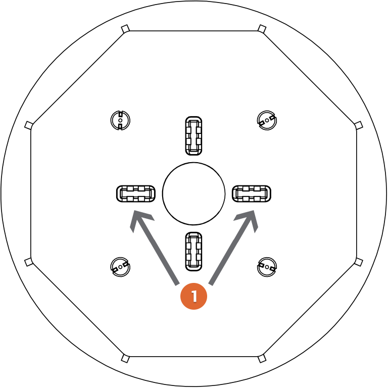
Remove 2 in-line or all 4 spacer tabs when needed.
Punch spacer tabs down with a hammer.
Remove 2 tile spacer tabs in line with one another atop each pedestal to allow the deck tile to be as close to the perimeter wall as possible. Pine tree fasteners may also need to be removed to accommodate the deck tile up against the perimeter wall.
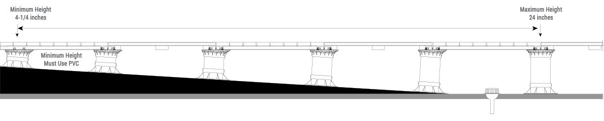
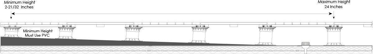
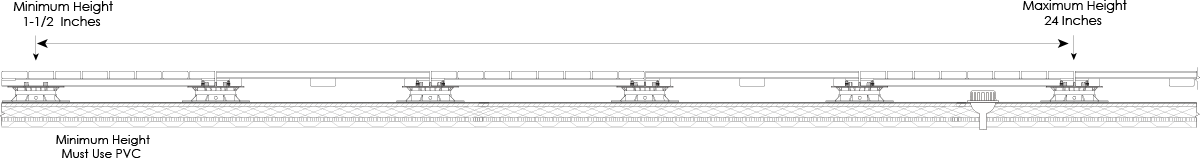
Altitudes Pedestal® System can be either fixed height or adjustable and will provide a slope up to 5% and a maximum height compensation up to 24 inches. Constructing a level hardwood deck tile surface over sloping substrates is accomplished by the following:
Thresholds will typically have the shortest pedestal height and will slope down toward drainage areas where the tallest pedestals will reside. Remove 2 spacer tabs (and pine tree fasteners) from the self-leveling pedestal heads to accommodate perimeter deck tiles. A 1/8th inch gap is the maximum space allowed between the threshold containment wall and deck tiles.
Radius installation will require additional pedestals to accommodate angular and curve-cut deck tiles. Additional pedestals must be ordered during the architectural planning. Remove spacer tabs where needed and use construction adhesive to secure radius tiles to the pedestal heads. A 1/8th inch gap is the maximum space allowed between the radius containment wall and radius deck tiles.
Spacer tabs and pine tree fasteners must be removed either by pairs or all 4 to accommodate irregular shaped deck tiles. Trimming pedestals is reserved specifically for the base – not the head. Trim the base as needed to fit.

Diagonal pedestal installation also requires additional pedestals to support deck tiles. Order additional pedestals during architectural planning; be sure to consult with the architect or building owner.
Use a high quality construction adhesive to fasten corner tiles to pedestal heads. A 1/8th inch maximum gap should not be exceeded between the perimeter containment wall and the diagonal deck tiles.
Spacer tabs as well as pine tree fasteners must be removed either by pairs or all 4 to accommodate cut deck tiles on angles. Do not trim pedestal heads; only trim the bottom of the screw-jack base to fit close to the containment wall.
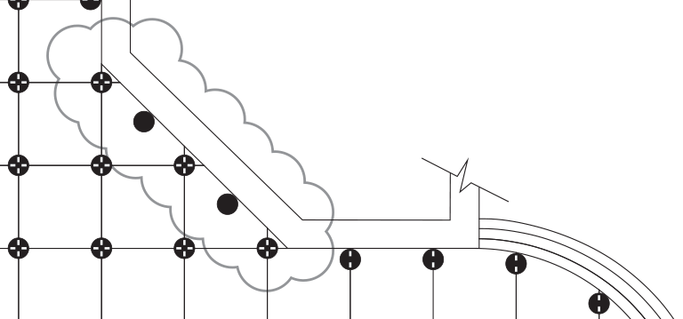
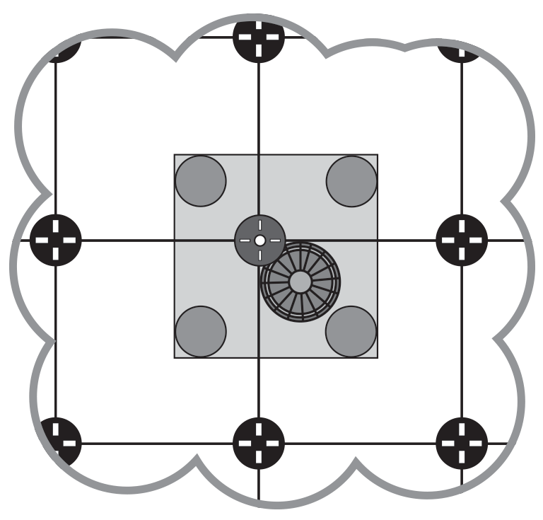
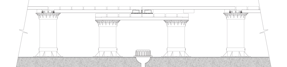
When a drain is located at or near a grid intersection for a pedestal, this may impede the installation of deck tile pedestals. Special steps must be taken to allow for proper drainage with additional pedestals and deck tiles.
Depending on the size of the drain area, 1-2 additional deck tiles will be used as a secondary base to “bridge” over the drain and act as a support for the “Top of Pedestal Elevation” deck tiles.
Place 4 (or more) pedestals around the drain to support a “bridge” deck tile ensuring adequate clearance between the drain and the bottom of the deck tile. This deck tile “bridge” will support the floating deck tiles above.
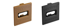
DeckWise® deck tile connectors – ordered separately – will be set on top of the deck tile “bridge” for proper gap spacing of the “Top of Pedestal Elevation” deck tiles. Secure the deck tile connectors to the “bridge” tile with stainless steel screws.
Cut the “bridge” pedestal PVC supports approximately 2-1/4 inches shorter than the “Top of Pedestal Elevation” surrounding pedestals. This measurement will accommodate for the thickness of the hardwood deck tile “bridge” over the drain, and allow enough screw-jack base threads for adjusting the “bridge” pedestal heights.
All 4 gap spacers should be punched into the pedestal heads and pine tree fasteners clipped with cutters for a flat surface. Each corner of the bridging deck tile should rest completely on each associated pedestal head. Be sure the stainless steel insert in the center of the drain pedestals are locked tight at the appropriate slope. Construction adhesive may be used for added support on top of each pedestal head.
Adjust the pedestals outside of the drain area with the screw-to-adjust base to accommodate for the deck tile connector thickness. Level all pedestal heads in accordance to the slope and “Top of Pedestal Elevation.
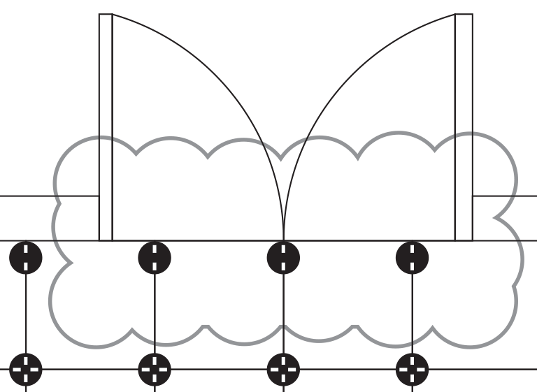
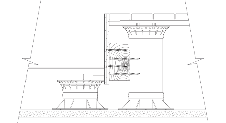
When a step down is needed, blocking and containment is vital to control possible lateral movement. A ledger board must be secured to the Schedule 40 PVC pipe of each pedestal along the step, onto each pedestal’s PVC support. Use stainless steel screws to fasten the ledger board onto the PVC followed by a fascia board to cover the ledger board. Secure the fascia board with stainless steel finish screws.
Always seek the professional advice of a licensed and accredited architect prior to installation.
ALL LOCAL AND STATE BUILDING CODES MUST BE ADHERED TO AT ALL TIMES.
Substrate protection should be installed prior to installing pedestals and hardwood deck tiles. The use of protection board, insulation, drainage mats, and waterproof membrane must be professionally installed and must meet or exceed local building codes before pedestal installation.
DO NOT use construction adhesive to secure pedestals to the substrate, insulation, roofing or waterproofing membrane.
The pedestal installer, contractor and or subcontractor assume the responsibility for the structural capability and acceptability of the installation structure to carry the dead and live load weight(s) involved. They must take into consideration all aspects of additional load from insulation, protection board, and waterproof membrane as well as keeping their integrity to perform up to manufacturer guidelines.
Altitudes Pedestal® System is specified to be used with pedestrian traffic only. Hardwood deck tiles cannot be allowed to move laterally. Retaining walls, blocking and perimeter containment walls must meet or exceed all local building codes.
The substrate installation surface to receive deck tiles and pedestals must be dirt free, oil free, moisture free and free of all foreign material. The installation area must have proper slope for water drainage and meet or exceed any and all local building codes.

We suggest you rely heavily on your design engineer and or architect to define the appropriate amount of pedestal and deck tile overage for the job. Deck tiles and pedestals are normally ordered with up to a 3% overage to compensate for corners, diagonal walls, radius installation and maintenance.
The deck/building owner must ensure decking inspections are made on a regular basis. Inspection of the deck tiles, supporting pedestals and underlying substrate must be in good condition. This is the time to adjust pedestals and deck tile levelness. Be sure there is no movement of pedestals or tiles. Adjust pedestals using the screw-to adjust- base. This is also a good time to check deck tile spacers and perimeter containment gaps to ensure they are within required guidelines.